Winding an S-90 pickup
The S-90 is my version
of a strat pickup like a P-90. This essay covers the conversion
of an inexpensive pickup (in this case a mexican fender singlecoil)
First thing that must
be done is to strip the pickup down to it's components. The
windings are cut off with an xacto knife. The pole pieces
are pushed out with a screwdriver, and the magnets are carefully
pried off. All glue is scraped from the magnets and the bobbin.
The eyelets are cleared of solder, and checked for rough spots
which might catch the wire durring winding (especially the
mounting holes!) The bobbins are then boiled in an attempt
to remove the wax (a little dish soap helps). The bobbins
now look like this.
These bobbins are
ideal for this conversion as they already have the ceramic
magnets preferred (alnico is generally too big or too weak),
and the solid bobbin makes the conversion to screw polepieces
easier.
Next step is to adapt
the bobbin to take screw polepieces. To do this I use nylon
bushings (3/16"x 1") which can be found at many
large hardware stores. Rough the sides of the bushings with
150 grit paper, and cut them in half. They are then coated
w/ thin superglue and inserted so they are flush with the
bobbin bottom. The bobbin should now look like this.
By cutting the bushings
in half it leaves them low enough in the openings that the
screw heads can be seated fully.
The bobbin is now
attached to the winder with heavy duty double sided tape,
and the wire attached. The wire(42 guage w/ poly nylon solderable
single build insulation is preferred) is wrapped half way
around the bobbin and taped to the top of the winder plate.
The end on top of the plate is sanded with 600 grit paper
(lightly!) and is used to check the resistance later. 
note the tape on top
of the faceplate
I manually wrap several
wraps to confirm the table height and depth stop are properly
adjusted so the wire stops just shy of the bobbin plates (aprox
1/16")at the ends of it's travel. The first several wraps
must run right against the bottom plate (guided with fingers)
to prevent future wraps from cutting it. It is ok to run the
wire across the bobbin at an angle as long as it's not too
great. The bobbin in the picture above has aproximately twenty
windings on it, the adjustments have been confirmed and it's
ready to be wound under power.
To begin winding I
confirm that the tensioner is slightly loose (see previous
page if unfamiliar with the setup I'm using) and turn
on the drill press. Now that it is running under power I increase
the tension to the correct level by tightening the tensioner
knob (I can actually hear a noise change in my setup when
the tension is slightly over) It actually requires more tension
than you would expect. Too much tension can stretch the wire,
increasing the resistance of the coil even if it doesn't break
the wire. Every once in a while I will use my fingers to guide
the wire closer to the bobbin plates to fill any gap due to
setting the travel short. This isn't always required as the
coil will spread as it builds up under tension. Simply use
the drill "press" function to spread the coil evenly
yet randomly. Care needs to be taken to not change direction
of travel too quickly as it will result in loose windings
at the edges. Once the bobbin is almost full the winder is
stopped. With 42 guage wire the bobbin will look like this
when it's about 6 k ohms resistance (a counter can be used
for reference, but coils should be wound to resistance)this
one actually tests at 5.75 k ohms

To test the resistance
the wire is sanded with the 600 grit paper with the wire held
against the "tensioner shelf". This bare spot is
then sprayed with laquer to reinsulate it (just in case it
should happen to contact a weak spot in the wires insulation
on the coil) The bobbin is then wound and retested until the
desired resistance is reached. For the best hum cancellation,
the coils should read within 5% of each other. For a strat
I typically wind the bridge pickup to 6.5, the middle to 6.25,
and the neck to 6; 5% of 6.25 is aproximately .30; I'm using
.25 for both the hum cancellation and an even change in output
from each position to account for the (relatively even) change
in string volume in each position. If a resistance above 7k
is required 43 guage wire must be used. Changing the wire
diameter affects the tone......
The wire tail is taped
to the bobbin, and the bobbin is now removed (remember to
remove the tape holding the wire to the winder faceplate first!).
The ends of the wire are sanded and then wrapped through the
eyelets. I tie a half hitch each wrap for added security.
It is then soldered. For this I use a 15watt pencil and melt
a drop of solder onto the tip (pointed tip) this way as soon
as the metal eyelet gets hot enough the solder flows into
place and I can see that it's done without applying excess
heat.
The screw polepieces
(allparts is a ready source of good ones) are now screwed
in fully. these screws are typically self tapping, cutting
threads as they go. I once tried to use the pole pieces from
a cheap Epiphone humbucker, but the shafts were too skinny
to engage the bushings.
The magnets are now
glued back on. Gel superglue or epoxy work well for this.
In a p-90 configuration the magnets are placed so the same
poles face the inside and rest against the polepieces. I use
a very cheap compass to check the polarity. The result looks
like this.

Note that the polarity
for the middle pickup (or second pickup in a 2 pickup guitar)
needs to be reversed for hum cancellation when combined with
the others.
I now attach the metal
plate typical of humbuckers. I will use the metal bar with
holes in it if I have one availiable which fits, In this case
I didn't have one, so I used bar stock. It doesn't really
matter as the screws do not engage the drilled bars either.
It now looks like this.

Next step is to attach
the lead wires. I use shielded wires in 22-24 guage. I use
the same method as before to attach the wires to the bobbin
Having tinned the wires already I do not need to add any additional
solder. The ground wire is attached to the baseplate using
a 40 watt soldering iron, and the plate is checked to ensure
the glue didn't come loose from the heat (it could be soldered
first). If this is a reverse polarity pickup I switch the
locations of the wires on the bobbin. resulting in a "reverse
wind" The reverse wind keeps the pickup in phase when
combined. This picture shows one normal and one "reverse
wound reverse polarity" pickup

The last step is to
pot the pickup. I've found that vinyl sanding sealer works
well, looks very clean, puts a shine on fiber bobbins, and
allows future repairs. It also has none of the risks or requirements
of wax potting. The drawback is it isn't suitable for potting
metal covers to prevent vibration, and it takes longer to
dry. I use the lead wires to suspend the pickup in the can
of sealer, and lightly pinch them in a drawer to hold it in
place.

It is left there until
no more bubbles appear. I use a soft bristle paintbrush to
wipe off excess sealer when the pickup is removed and set
the pickup on a paper towel to dry. In it's normal use the
sealer dries in under 1 hr. I leave it overnight.
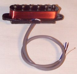
The finished S-90
pickup! Everyone LOVES these S-90's, why not make one for
yourself?


