Pole A-D : This is the pole of the switch - the part that is ALWAYS connected - you are connecting the Pole TO something (a throw)
Throw 1-6 : these are the 6 individual positions with different connections for each ‘throw’
OUT : This is where your output will come from, think of this as a bus (an electrically common place). So you could, for instance, run a wire across most of the lugs on pole A (the top wafer of the switch). Then you could jumper a wire from C6 up there to the “Out bus”. Now for output, you just have to run a wire from the bus to your volume or whatever.
GND : this is ground, since you might be wiring two pickups
in series, etc through another switch - I’d suggest doing the ‘bus’
trick,, that way you only have 1 wire to solder to a pot and you can install/remove
the thing without having a rat’s nest.
In the case of running into another series switch, the GND might Not go
to ground, but to another switch. A more accurate designation might be
COM - (negative common). The term Neg is purely phase, since the signal
is AC there isn’t really a negative
N.C. : No Connection - you can put these to ground, but you don’t need to. Standard switches don’t go to ground. Some Electrical engineers do because they are user to CMOS computer chips; for guitar it’s nonsense.
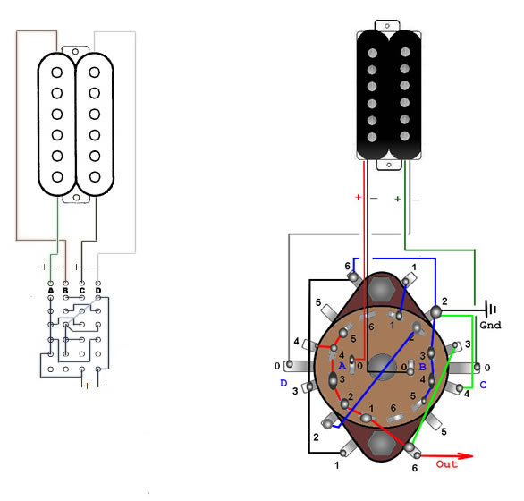
These drawings show a "connection diagram" on the left, and the wiring of the six way 4 pole rotary availiable from Allparts. This switch is a stacked dual wafer design...